The short shot moulding process is usually applied to tubular style mouldings or mouldings that have large gas channels compared with the surrounding wall section.
The size of the gas channels are best kept to below a 25mm flow diameter but can be made bigger. It becomes progressively more difficult to control the plastic flow above 25mm diameter so this places restrictions on the design and surface finish.
Care must be taken with the gate design as it is difficult to inject plastic into such a thick section without jetting or folding of the plastic flow. Jetting and folding will cause flow marks on the outer surface of the part.
Plastic packing is not possible as the cavity is only partially filled with plastic prior to gas injection.
Short shot mouldings are filled to less than 100% of mould cavity volume with plastic before gas injection. Gas is then injected to displace the hot core of plastic forward completing the filling of the cavity. Once the cavity is filled the gas continues to flow into the gas channel as it packs the plastic. Initial gas flow into the cavity needs to be very high.
The rate of flow of the gas is controlled by the resistance of the plastic being displaced into unfilled areas. During packing the gas flow into the component is controlled by the rate of the shrinkage of the material as with Full Shot Moulding. The gas flow rate during plastic packing is very low.
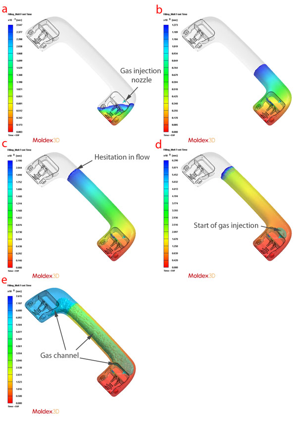
The pictures show the results of a 3D flow analysis of a grab handle completed by us. The analysis allowed our customer to optimise the plastic and gas injection locations before the tooling was produced. The analysis allowed flow marks and weld lines to be avoided and the gas channel position and length to be optimised.
Shot shot moulding step by step:
a The plastic gate needs to be located at the same end as the gas injection location. The gate needs to be designed to inject the plastic without jetting or folding of the plastic flow front.
b It is important that the plastic quickly makes contact with the outer walls of the mould and fountain flow occurs. The plastic will flow from the point of injection towards the last area to fill.
c There can be hesitation in plastic flow into the cavity at the position where plastic injection finishes. This is caused by a delay in gas flow into the cavity. This delay can be caused by process settings or can be necessary to control the gas flow through the plastic. This area is usually called the hesitation line or position.
d Gas is injected into the cavity using the minimum delay possible to avoid hesitation in the plastic flow. The gas must be injected directly into the centre of the thick section to be cored with gas. It is also important that the gas injection nozzle is designed for the high gas flow rates required.
e Gas flow length is controlled by the amount of plastic injected. If too much plastic is injected the gas will not flow far enough through the cavity. If too little plastic is injected the gas will escape out of the flow front before the cavity is filled.
Advantages
> Offers the simplest method of gas injection moulding
> Offers the biggest gas core size
> Produces the lowest clamp tonnage requirement as the cavity is only partialy filled with plastic before gas injection.
> Applies equal packing pressure (gas at equal pressure)
> Reduces warp/distortion
For more information please contact us.
Limitations
> Low plastic injection pressure can reduce the cosmetic appearance
> No plastic packing can cause sink over injection moulding features with some designs and reduces the quality of the surface finish
> Inconsistent surface finish especially with glass filled materials
> the possibility of a hesitation line between the end of plastic fill and gas injection
> No process control over the wall section, the wall section is a result of the component cross section and the material used