The full shot moulding process is usually applied to injection moulding style components that have thick ribs and features that cannot be packed using traditional plastic packing.
> Wall thickness is usually between 2 and 4mm
> Ribs and thick sections between 2 and 6mm
Gas channels will need to be added to the underside of ribs and features to control the gas flow into areas that require gas packing.
The considerations given to the plastic filling phase are the same as with injection moulding. The filling pattern needs to be designed to avoid weld lines, flow marks and air traps.
A full shot moulding is filled to at least 100% of mould cavity volume with plastic during the plastic filling stage.
Depending on the design and plastic used a small amount of plastic packing can be used.
Plastic packing will reduce the shrinkage of the material in the cavity and in turn reduce the gas flow into the component.
Gas is then injected after a short delay and flows into the component to compensate for the plastic shrinkage. The rate of flow of gas into the component is controlled by the rate of plastic shrinkage. The amount of gas flow into the component is controlled by the plastic volume shrinkage.
The amount of shrinkage within the plastic will vary dependent on the type of plastic used, its pressure and temperature at the end of plastic injection.
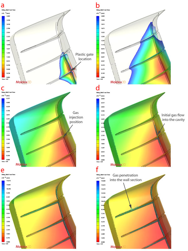
The pictures show the results of the flow analysis of a cover component that has thick sectioned rib features that require gas packing.
The flow analysis by us allowed the component to be successfully modified by our customer for gas injection moulding using the “full shot process.”
Full shot moulding step by step:
a The plastic gate location has to be designed to fill the part evenly leaving the last areas to fill at the far ends of the cavity.
b The plastic flow will accelerate in the thicker gas channels. Care needs to be taken to avoid this acceleration causing weld lines, flow marks or air traps.
c In this case the gas injection location is close to the plastic gate. The gas injection location must be designed to control the path the gas takes through the component. Placing the gas nozzle in the wrong location will have a direct effect on the position and length of the gas flow through the component.
d The gas starts to flow into the cavity from the nozzle as the plastic starts to shrink. The rate of gas flow into the cavity is rolled by the rate of shrinkage of the material.
e The gas flows towards areas of high shrinkage taking the path of least resistance. The path of least resistance is designed to be the thickened area at the base of the existing ribs. If these thickened areas/gas channels are not sized correctly gas will not flow the required length or could penetrate into the wall section.
f If the process is not applied correctly the gas can flow out of the gas channels into the surrounding wall section in an uncontrolled manner. The design of the part, the layout of the gas channels and the process settings all have a effect on controlling the gas flow within the gas channels.
Advantages
> Removes sink marks from thick sectioned ribs and features
> Gas packing can eliminate distortion caused by unequal plastic
packing pressure
> Can be successfully applied to all plastic materials including
ABS, PS, Nylon and PP
> One of the simplest methods of gas injection moulding
> Maximum volume of gas core (up to 20%)
> Can reduce clamp tonnage requirement
> No hesitation in the plastic filling pattern
For more information please contact us.
Limitations
> Plastic shrinkage controls the amount of gas flow into the component
> The plastic shrinkage/gas flow places restrictions on design, you must design for the process
> Smaller gas channels than the other process options, less structure
> Very limited plastic packing of traditional injection moulding features